TDA7293 TDA7294 based Composite amplifiers
Being impressed by the beauty of the sound of composite amplifiers based on LM1875, I put some effort into designing a composite amplifier based on TDA7293 or TDA7294. I hoped to achieve the ultra low distortion and noise of the LM1875 composite. After some ups and downs I managed to build a TDA7293 or TDA7294 composite amplifier achieving the perfect sound of LM1875 but capable of providing a lot more power.
The TDA7293 TDA7294 ICs use a MOSFET power stage, whereas LM1875 uses bipolar transistors. The main benefit of the MOSFET stage is that it doesn’t need such radical protection circuitry as a bipolar stage, so unpleasant protection circuit artifacts are eliminated. Another advantage of using MOSFET output transistors is the increased output power since the remaining voltage is less in comparison to bipolar output transistors.
The TDA7293 TDA7294 is a very capable amplifier, and makes a very good account of itself. It’s been used in a number of commercial products and many, many DIY projects. It has a bewildering number of options, even allowing you to use different power supplies for the input and output stage or using another TDA7293 as a second power stage. Another possibility of using TDA7293 is in a Class-G design, with external transistors. It’s a complex arrangement that I have not built.
During the years I have built and tried a great number of different designs utilizing TDA7293 or TDA7294. Some of them had very decent sound (and low THD) some not, but they all had one thing in common which I call “TDA7293 / TDA7294 sound”. It does not mean that it is necessarily a bad thing, some people love that sound. For me it has always been inseparable from listening fatigue.
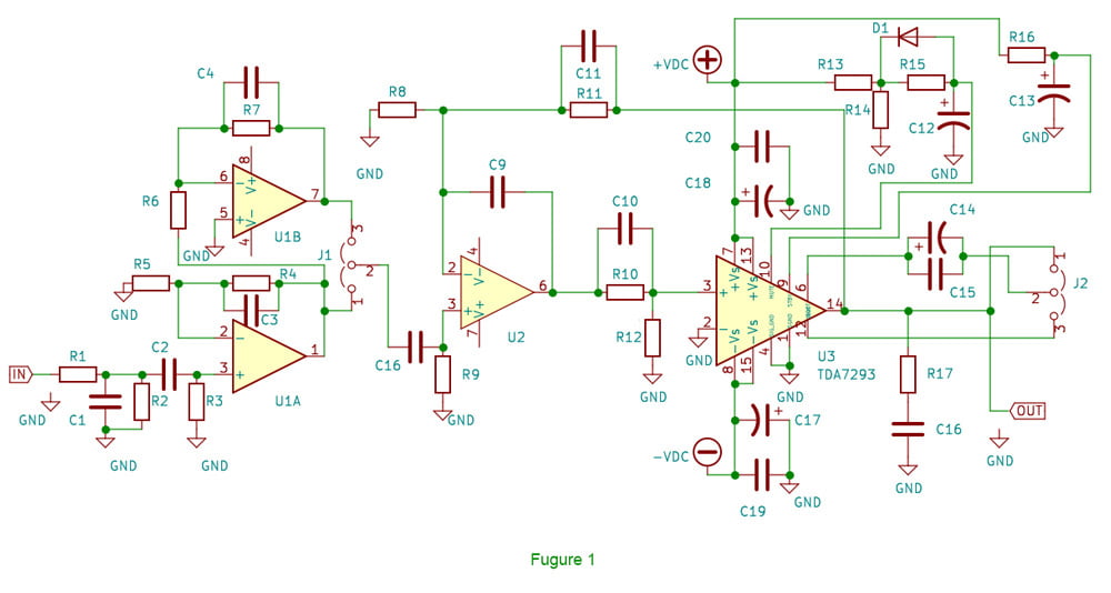
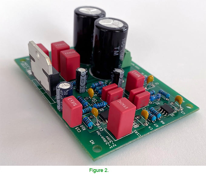
When designing the composite amplifier the open loop gain and phase shift vs frequency plots are of great help. Unfortunately the data sheets of TDA7293 / TDA7294 lack the open loop gain and phase shift vs frequency data, which did not make the task easier but anyway the complete circuit of a composite amplifier based on TDA7293 or TDA7294 is shown on Figure 1. The practical implementation is shown on Figure 2.
Before discussing the results, I’m going to say in advance that the characteristic sound of TDA7293/94 and listening fatigue have both gone. That simple design has turned TDA7293/94 into a real HI-End amplifier successfully competing with many famous (including the price tag) power amplifiers. For more information look at the section of Sound Quality.
The circuit shown on Figure 1 consists of two independence circuits – a composite amplifier (U2 and U3) and small preamp (U1). The composite amp circuit is similar to the one described in the LM1875 composite amplifier project. The gain of that stage is 11 but can be adjusted from 5 to 20. The role of J2 is to allow the use of either TDA7293 or TDA7294. The function of the preamp is to ensure gain of 2 and provides a possibility to invert the input signal in case we want to use the amplifier in BTL configuration. The preamp defines the bandwidth (4-5Hz to 150kHz) as well. To ensure low distortion and low noise floor U1 needs to be a high performance op amp.
Figure 3 shows THD + noise plots vs output power. The PSU is identical to that used with LM1875 composite amplifier but the output voltage is ±33.5V.
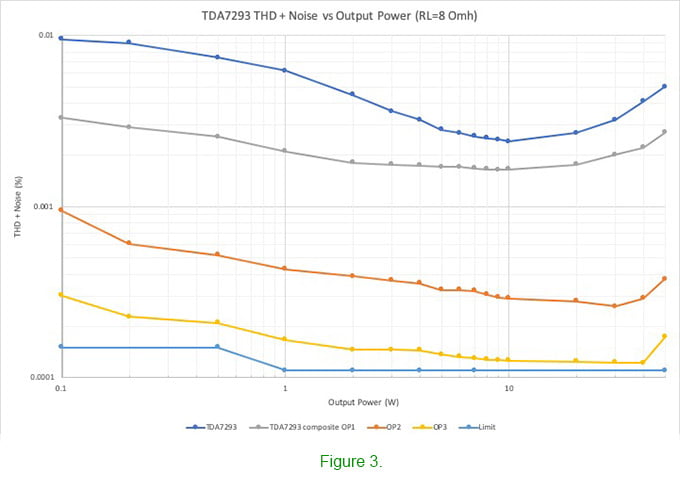
The first plot shows the THD and noise of TDA7293 implemented in a circuit very similar to that shown in the data sheet. Like LM1875, here the thermal feedback distortions at low output power are present as well. As it was mentioned earlier the sound quality of TDA7293 was remarkably improved in the composite circuit and it is well correlated to the improvement of the THD and noise figures. The choice of the op amp is very important. The effect of different op amps in the composite circuit is shown as well. The output DC offset is typically 1 mV or less.
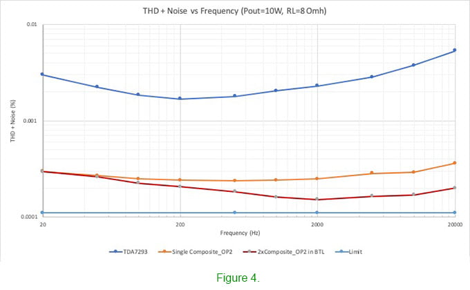
Figure 4 shows the THD and noise plots vs frequency. The plot of the BTL configuration is shown as well. The lower THD in this case is most probably due to cancelation of some even harmonics.
Power supply requirements
The power supply requirements here are the same as those described in the LM1875 composite amplifier with the exception that the supply voltage and output power respectively can be much higher. All measurements were done using regulated ±33.5V Switching Power Supply able to deliver approximately 15A continuous current with 40mVp-p ripple. I have experimented with a “conventional” power supply ±36.0V (200VA toroidal transformer, diode rectifier and 2×10,000uF capacitors) and could not find any significant differences. I have not tried supply voltages higher than ±36.0V since the output power above 55-60W requires special attention to the excessive heat released by the IC chip.
PCB Layout requirements and parts selection
This section is the same as that described in the LM1875 composite amplifier.
Output Power
TDA7293 is a very versatile IC chip. According to the data sheet it is able to provide 100W output power and the supply voltage can be as high as ±50.0V. I never pushed the chip till such extremes. The table below summarizes the relation between output power (Rl = 8 Ohm) and ±Vss.
Table 2. TDA7293 TDA7294 output power (Rl=8 Ohm) vs power supply.
Output power Supply voltage
20W ±20.0V
30W ±24.0V
40W ±27.5V
50W ±30.0V
60W ±33.5V
For 2x60W version 180-200W transformer is more than enough.
Don’t use supply voltage higher than required for your output power needs. In this way you can save money from the price of the transformer and capacitors for example and your amp will run cooler. There is not much benefit in using an oversized transformer as well.
Switching power supplies are very welcome as well but they need to be able to provide low noise and ripple. The Meanwell LRS series is a very reasonable choice but you need to combine two of them to get ±Vss.
Requirements for the operational amplifiers power supply are the same as those in LM1875 composite and there should not be any compromises if you aim at the lowest possible noise. If not, a very reasonable solution is a well built LM317 / LM337 voltage regulator or the improved LM317 / LM337 version shown in the LM1875 composite amplifier.
High power versionS
As mentioned above, it is not recommended to draw more than 60W from TDA7293 TDA7294. For those in need of more power there are many different options. The simplest one is to bridge two composites. In this way 100 – 110W (Rl = 8 ohm) output power is the best you can get. Unfortunately this won’t work with 4 Ohm speakers. Paralleling two composites would provide 100 – 110W output power into 4 Ohm speakers. Bringing two parallel composites would easily provide 200W into 8 Ohm speakers.
According to the data sheet there is another option of paralleling TDA7293. The circuit of a composite amplifier utilizing this option is shown on Figure 5.
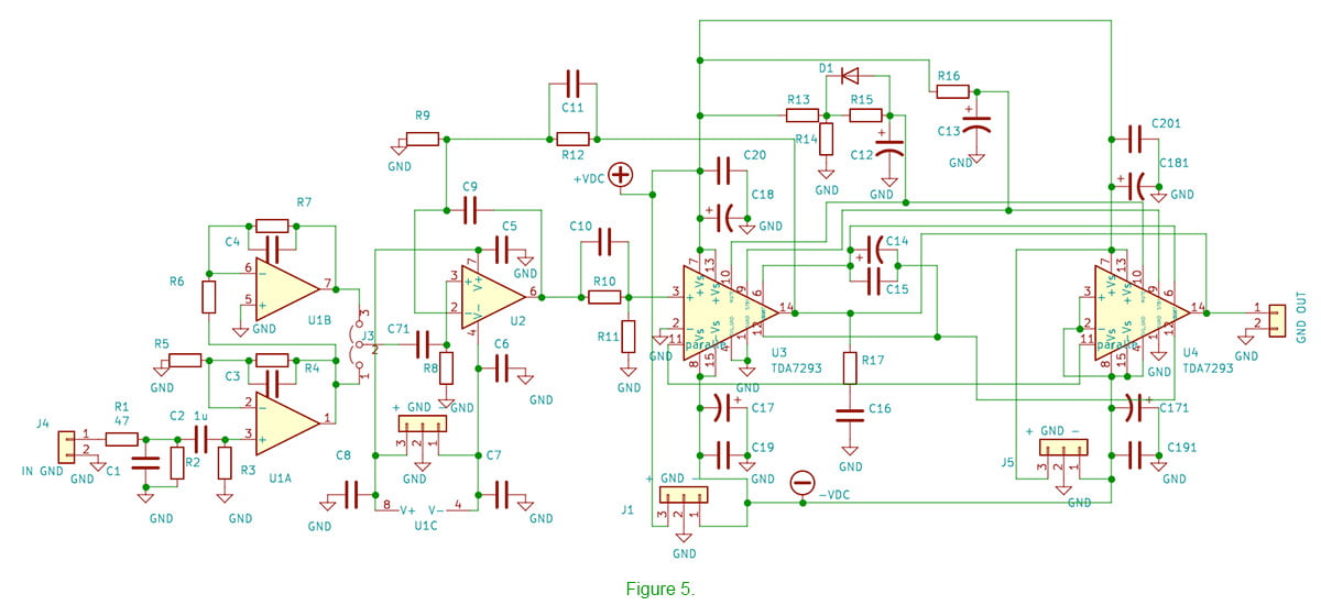
This implementation is a good alternative to paralleling two composites. THD + noise plot is almost identical to the single TDA7293 composite version but the output power into 4 Ohm speakers could be 100-110W. Here I should mention that the THD plot of two composites in parallel is equal to (or little bit above of) the noise floor of the measuring equipment i.e. around -118dB.
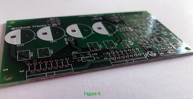
The PCB of the circuit shown on Figure 5 is shown on Figure 6.
Sound quality
The sound quality of the composite amplifier based on TDA7293 TDA7294, as I already mentioned above, is supreme. That simple design (especially BTL configuration) has turned TDA7293 TDA7294 into a wonderful HI-End amplifier successfully competing with many famous (including the price tag) power amplifiers. Since my main setup is based on 4-way active speakers to compare the composite to other amplifiers I had to bring it to friends or people who I know. Usually people know very well the sound of their own system so blind comparison was not possible. Anyway, the vast majority of the people who have heard that composite amplifier recognized its merits.
How does the sound quality of the composite amplifiers based on TDA7293 TDA7294 compares to that of the composite based on LM1875? Both amplifiers have similar very low THD and noise. At very low power (0.5 – 1.0W) it is really difficult to find any difference. Increasing the output power (5-10W) however makes some sight differences visible (hearable). Blind tests pushed the scale a little bit in favor of TDA7293 composite but not in all genres of music.