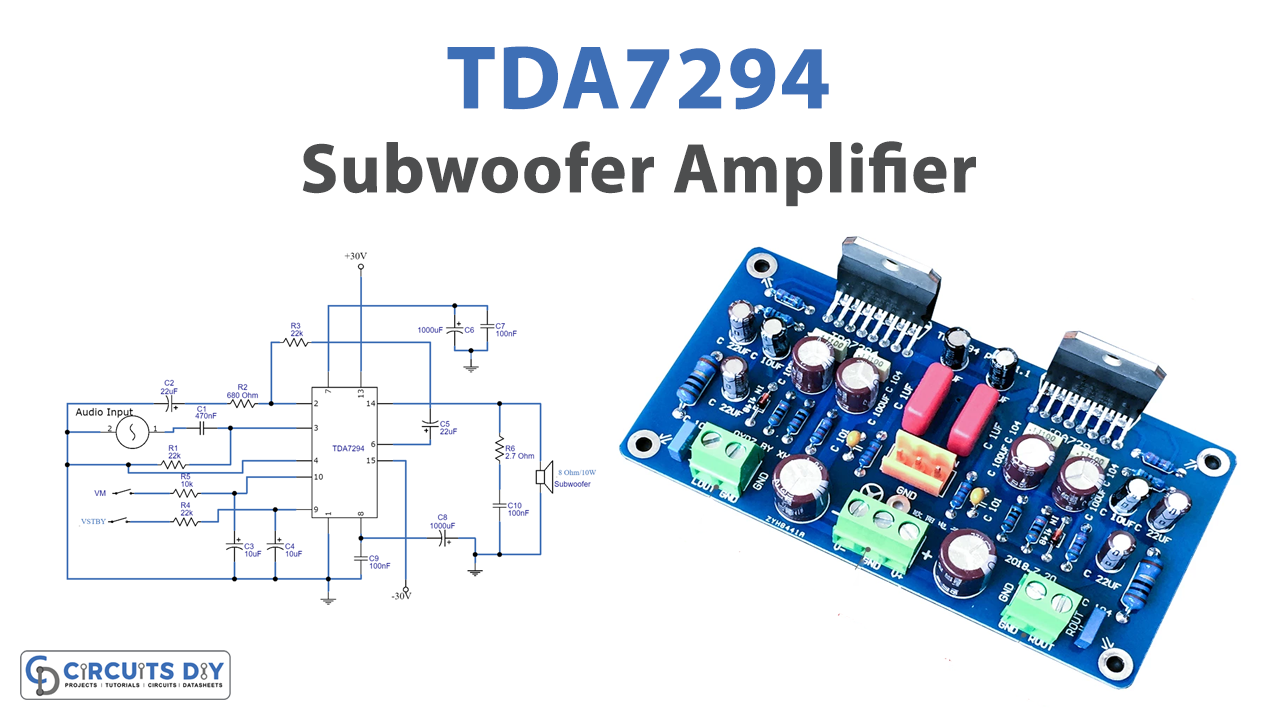
An audio amplifier is a circuit that transforms the small amplitude of audio input signals into a large amplitude audio signal at the output. In this tutorial, we are going to “TDA7294 Subwoofer Amplifier Circuit”. A subwoofer amplifier circuit is essentially a loudspeaker that generates low-frequency audio signals. These circuits effectively boost the quality of audio signals and improve their bass. This circuit is highly beneficial for producing low-tone frequencies.
The TDA7294 IC is used to make an audio amplifier in this article. It’s a class AB amplifier by design. It has a high level of ripple rejection. Low noise and distortion are supported by the IC. It includes a built-in thermal shutdown that guards against short circuits. The circuit, however, requires a heat sink. The integrated circuit’s frequency response ranges from 20Hz to 20KHz. Use an 8-ohm, 15-watt speaker as the load in the circuit. It’s important to remember to use a filtered power supply. Because supply ripples can induce oscillations,
Hardware Required
| S.no | Component | Value | Qty |
|---|---|---|---|
| 1. | DMOS Audio Amplifier IC | TDA7294 | 1 |
| 2. | Speaker | 8Ω | 1 |
| 3. | Battery | 30V | 1 |
| 4. | Capacitor | 22uF, 10uF, 100uF, 1000uF | 2, 2, 1, 1 |
| 5. | Resistors | 10KΩ, 22KΩ, 680Ω, 2.7Ω | 1, 3, 1, 1 |
| 6. | Ceramic Capacitor | 470nF, 100nF | 1, 3 |
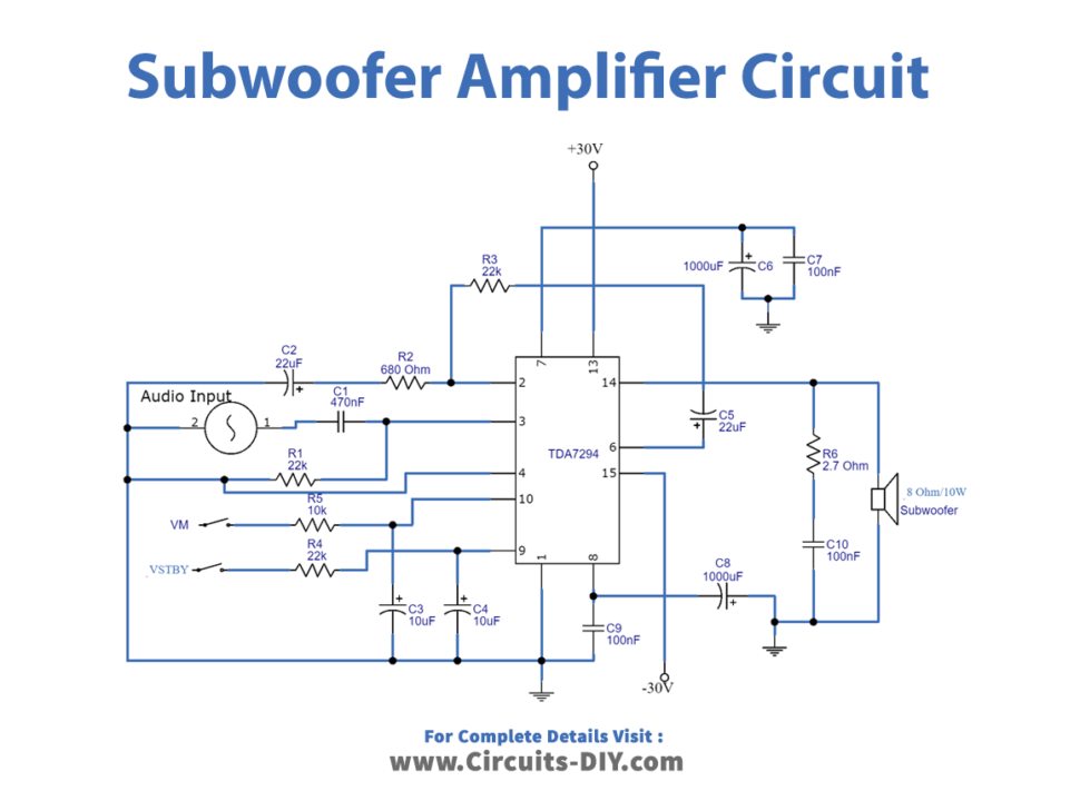
Circuit Diagram
Pinouts of TDA7294
| Pin No. | Pin Name | Pin Description |
| 1 | Stand-By GND | Stand-By GND, the output gets connected to ground |
| 2 | Inverting input | The Inverting input |
| 3 | Non-Inverting input | The Non-Inverting input |
| 4 | SVR | Supply Voltage Rejection is used for power supply ripple or noise rejection |
| 5 | N.C. | Not connected |
| 6 | Bootstrap | Used to step-up charge |
| 7 | +Vs Supply | Positive supply |
| 8 | -Vs Supply | Negative supply |
| 9 | Stand-by | Standby control pin used for low power mode, output runs in low current mode |
| 10 | Mute | Audio is disabled in the output |
| 11 | N.C. | Not connected |
| 12 | N.C. | Not connected |
| 13 | +Vs Power | Positive power supply |
| 14 | Out | Output pin |
| 15 | -Vs Power | Negative power supply |
Working Explanation
The TDA7294 Subwoofer Amplifier Circuit uses the IC having 15pins. VM represents the mute ON and OFF voltages, which are 1.5V and 3.5V respectively in the circuit. The standby ON and OFF voltages are 1.5 volts and 3.5 volts, respectively, in VSTBY.
We attach the input coupling capacitor C8 to the non-inverting pin of the IC and serve as an input coupling capacitor. The bypass capacitors are capacitors C10C10 and C4. While C9 and C3 are power supply filter capacitors. The mute and standby switches are at S1 and S2, respectively. The feedback capacitor is C2, which is shorted between pins 14 and 6. As the load, we connect the speaker to pin 6 of the IC. When we provide the low audio input at the pin, it gives us the amplified output at the load.
Application and Uses
- Digital theatre systems deliver high-quality, noise-free high-bass music.
- It’s also employed for long-range transmission.
- In movie theatres, it’s utilized to make a loud bang to get people’s attention.